Thursday, October 29, 2015

Week 8: Day 025 - Installing a Physical Network #7


This is it folks, the end... today I will finally finish this chapter! After like 50 something pages of this, the end is here. Today's entry won't be the familiar long ones you usually see, cause there aren't that many pages left. To be brief, there's only one section left. The next chapter, may be about the same length, but I will hopefully get through it quicker.

Firstly, this final section is about Diagnostics and the (sigh) Repair of Physical Cabling. So first, if your network fails, you gotta diagnose the issue! Usually when it tells you that "No server is found" or network explorer/network is being used by the OS to find the issue, then it's a physical problem. First you should try to rule out software errors. It's pretty easy, if one application is working, and another isn't, then bam, it's a software problem. When the systems fail to access the network, then it would be a good idea to suspect the switch as the issue. Also, throwback to the link lights, that's also one of the best tools you have in diagnosing the problem. If the lights aren't on, somethings not connected. If the machine is isolated in its issue, compared to other devices, then you know it's not a problem with the switch. Sometimes a good idea is to bring a patch cable to plug the system into a good outlet. Next, you would obviously check the NIC at some point. A bad NIC can be the cause of the "can't see network" problem. Using the utility on your operating system is a great tool in seeing if you have a bad NIC. The female connector is many times the root of the problem there. To test that, the NIC has the "loopback test". Despite the tediousness, it's important to remember to check all these things.

Although many of the problems are in the work area, sometimes you'll find that the horizontal cabling is to blame. To test this, you'll need a mid-range tester. Patience is a big requirement for this, and I'll be honest, I'm not a very patient person. Important note, always include the patch cables in the test. If the problem is horizontal cabling, it's hard to fix, so just replace it haha. In the TR (Telecommunications Room) you'll find that it's a big maze, even if it's organised. The punchline here is test every cable, don't skip a connection. All the boxes need a good amount of power, which is a big concern for your TR. What these power supplies are called, is UPS (untierruptible power supply) no, not the postage company! A "voltage event recorder" is useful for these things, because if you lose power to them, it will record what the issue is with the UPS. The temperature in the TR should also be monitored just in case it gets to hot and your computers overheat. One way of doing this easily, is with a "temperature monitor". As for humidity and other stuff use an "environmental monitor".

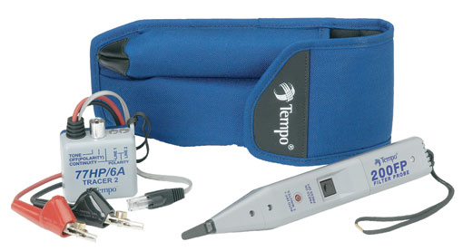
Finally, let's be honest, there will come a time during the construction of a network, when something goes wrong when organizing, and maybe later on you'll regret it. For example, if a label falls off, or if you miscount the amount of rows. A lot of things could go wrong in that aspect, and you should be ready for it. When you must trace a cable, there is a device called a "toner" which helps with this. However, this word is a reference to two different devices. The "tone generator" and the "tone probe". To trace a cable, connect the tone generator to the end of the cable, and then the tone probe to the other end of the cable. This will test the cable, and hurrah you're finished! Haha, SO AM I. This chapter is over, done, Get ready for some TCP/IP next time!!! Thanks for reading, and goodbye.

Monday, October 26, 2015

Week 8: Day 024 - Installing a Physical Network #6


Hello, it's a new week, and there's not that much left in this chapter, thankfully! I'm really eager to get onto the TCP/IP part of the textbook (which is next.) Anyways, today we're going to go into some NIC related stuff, fun!

So as we know from before NIC stands for "Network Interface Controller" and the textbook characterizes this as the "final part of any physical network". All UTP Ethernet NICs have the RJ-45 connector, which is connected from the NIC to the switch. Now, when it comes to fiber-optic NICs, they come in variety. Manufacturers like to use the same connectors for the multiple standards, which causes confusion. So a 100BaseFX card used for multimode with an SC, and an identicle card for single-mode also uses an SC connector. The only way of telling them apart is the documentation!

When you're looking to buy a NIC, Mike Meyers suggests buying from brand names such as Intel, because they're reliable, have more features, and are easy to return if they're defective. He also points out that, replacing missing drivers on a brand name NIC is also easier (which I would imagine.) But the NIC you choose depends on the network. If you can afford it, get multispped cards, and stick withthe same model. The more models you're using, the more driver discs you'll be carrying around (which sucks.) So all in all, I would have to agree with this assessment, go with the brand name NICs!

The physical connections in a computer are not magical, so if the NIC is not connected to the computer, the NIC will not work! Fortunately, most of the time the NIC is built in to the PC you purchase. Usually there will be a couple expansions slots in the computer. One of them is older, but more common, and it's known as PCI (Peripheral component Interconnect.) The newer one is PCIe (PCI Express) which are used more widely nowadays. They come in one-lane or two-lane varieties, and I have no clue what that is haha. If you're so lazy that you won't open up the PC case, you can be lazy, and get a NIC with USB and PC Card ocnnections. However USB 2.0 is not as good as gigabit ethernet, so it's a dumb idea to use that, and PC Card is exclusively for laptops. But a USB 3.0 NIC are brilliant and handles speeds up to 5 Gbps, so there's no problem with those. These USB NICs come in handy when you must troubleshoot whether the machine you're dealing with has a bad NIC or not.

Next, there are the NIC drivers that must be installed onto the OS of the machine. It's very easy, just put in the CD, go through the installation, and you're done. Sometimes, it might even already have the driver installed. Every OS has its own way of identifying the existence of the NIC. Then once you've done that, an important thing to note is that two NICs can actually be used on the same computer! The process to achieve this is called "bonding" or "link aggregation". Basically it doubles the speed between a machine and the switch, so happy days.

Finally, there's link lights. Every UTP NICs have LEDs (Light-emitting diodes) which give information about the status of the link between the switch and the machine. Even though you may know that it's an LED, call it link lights. NICs have four link lights and they can be any color. They literally tell you what may be wrong with the system's connection. More specifically, a link light tells you that the NIC is connected to a switch, and the switches themselves also have link lights. If one of the computers on the network are telling you that it's disconnected, consult the link lights first. When it's functioning correctly, the link light is on and is steady. This means NO flickering, just on. Then there's the "activity light", which turns on when the card detects traffic on the network. The light is great for detecting problems, because the connection light is sometimes fraudulent in it's claims. If the connection light says it's fine, try to copy files, create network traffic somehow, and if the activity light doesn't flicker, then you know there's a problem. On older NICs there is the "collision light", which flickers when there are collisions on the network. It may not be important, but it could be on the exam. There is no standards on the NIC lights, so manufacturers created many varieties of it. When you see a new NIC with different lights, figure out what each one means. It's always going to be the same: link, activity, and speed. When it comes to fiber-optic NICs, they don't have lights! This make troubleshooting a harder task. To add on to this, the cabling itself is very delicate. People that work with fiber have testers of their own, as I said earlier in the chapter. Honestly, it probably doesn't matter much to me, but it's something to note. That ends the section on NICs, tomorrow will be a shorter entry, since I will be doing the final section! On that bombshell, thanks for reading, and goodbye!


Friday, October 23, 2015

Week 7: Day 023 - Lab Router #2


 Well after all that complaining about the bus, it showed up on time today! But I barely made it on the bus, the door literally shut behind. It's because my class is across the school from the bus ramp. Anyways, I got here on time (for once) and am now going to set up this lab router!

Firstly, I showed up on time, got the CD from my teacher and then inserted the disc into the drive and started burning the iso image for Ubuntu Server onto the CD through Xfburn which is pretty nifty for this OS. Once the installation finished, I went to the computer which will be turned into a router.

When I booted it up, it was still on that drive which was set to the cigar shop thingy, so I then I went back to the boot options in the bios and set it for the DVD drive, since that's where the CD was in. Apparently it's got a terabyte worth of space! It then started up the installation wizard for the Ubuntu Server software. I went through the process, my teacher partitioned it for me, since it was dumb to commit 1 terabyte to that one server. But during the process, I came across a brick wall when trying to set up with DHCP client with the server. I guess I'm not ready for that stuff until later. I skipped that, and finally got to the end of the installation, and that was it.

After, I finish my chapter on Installing a Physical Network, the next one will be revisiting TCP/IP in a more in depth manner. Perhaps during that chapter, I will better understand the theory for some of these things, to help me test the server in the lab at the back of the room. Until then, I won't be doing much with this thing... so on that bombshell, goodbye!

Wednesday, October 21, 2015

Week 7: Day 022 - Lab Router #1


Well, my bus decided to show up extremely late today, so I got to the Career Center very late! I swear, I'm gonna file a complaint with these guys, how can I be getting to class 45 minutes late! Hopefully this doesn't occur again, cause things are getting interesting for me in this class, as you will see.

Anyways, today my teacher gave me a computer to perhaps become a router, and a DHCP server. It's a really old computer, so much so that he didn't know what was on it. I booted it up, and the boot priority was set to a floppy disk... you heard me right. A FLOPPY DISK! Crazy as it was, I went into the bios and I told it to set the CD drive as priority boot, and it booted up with a boot screen that had Ubuntu listed as one of the boot options. I load it up, and it thinks it's 2001! It looked like quite an old version of Ubuntu as well.

According to my teacher it was actually a hard drive that was thrown in several years later, for some guy who wanted a cash register at a Cigar shop. Yeah, kind of weird... So after that, he told me that I should go to my workstation and download an iso for ubuntu server, and then burn it onto a CD. I'm downloading it now as I type, but I'll probably burn it next class. Following that, I'll be installing that CD onto the old computer I've been banging on about. This is going to be a new experience for me, and he said I'll be setting up the server myself. When I finish, it should be able to shut down all computers in the lab, on command. Sounds cool to me, honestly.

This is another short entry, compared to my other ones, but of course understandably, considering my bus got here very late. On that note, this entry is over! I'll be continuing the "Installing a Physical Network" segment shortly. Thanks for reading, and goodbye!

Tuesday, October 20, 2015

Week 7: Day 021 - Installing a Physical Network #5


We're five posts into this chapter, and still not finished! To keep up pace, I'm gonna wanna finish this chapter quicker I would say. Thankfully, I'm not too stressed out with other classes as of now, so it shouldn't be too difficult to get back to my former pace.

Last time, I finished talking about Telecommunications Room and Making Connections. Today, I'm moving on to Testing Cable Runs. After you've completed the installation of the horizontal cabling, the best course of action is to see if all the jacks are plugged in, and then test the cable runs and assess their speeds. That's great and all, but network testing equipment can cost thousands of $$$ which sucks. However, there are less expensive ways of testing your network. According to my textbook here are some good questions to ask when dealing with potentially bad cables:

- How long is this cable? If it's too long, the signal will degrade to the point that it's no longer detectable on the other end.
- Are any of the wires broken or not connected in the crimp? If a wire is broken, it no longer has continuity (a complete, functioning connection).
- If there's a a break, where is it? It's much easier to fix if the location is detectable.
-  Are all of the wires terminated in the right place in the plug or jack?
- Is there electrical or audio interference from outside sources? UTP is susceptible to electromagnetic interference.
- Is the signal from any of the pairs in the same cable interfering with another pair?

In response to those questions, you must use a cable tester to answer them. Some are better than other, and can also answer more of those questions than others. Continuity testers are the economy ones, which are under $100, problem though is that it requires both ends to be connected in there (and I'm sure you don't want to unplug all those cables!) Now the more expensive testers run "wiremap" tests that pick up shorts and cross wires. The multimeter, which I've actually used before, is good to testing continuity. If there is no conneciton, you'll get infinite Ohms. So medium-priced tester cost around $400 and determine not only continuity and wiremap, but also the length of the cable! In addition to that, also if there's a break on any of the wire strands. One great advantage is that the tester works with already installed cables, so no unplugging. The more expensive ones detect some really specific issues, such as crosstalk, which is when when one of the UTP wires sends a signal, and the other wires pick up some of it (because they're so tightly closed together.) When crimping you should be wary, because a bad crimp will make it so the cable cannot do top speed due to a lot of crosstalk. To test the crosstalk the tester does a "near-end crosstalk" (NEXT) which detects and measures the amount of interferences on the near end of the connection. It also does a "far-end crosstalk" (FEXT) which listens on the far end of the connection. Other problems that occur in cables is "attenuation" which is when the signal gets weaker. When a cable run gets longer, there's more attenuation, unfortunately. To verify every cable run meets the TIA/EIA standards, tools known as "cable certifiers" are used. Most network techs will never use that (cause they don't need it!)

Finally, I want to go over testing fiber. In terms of testing, this is a very different thing. Fiber-optic technicians have to perform termination on the cables, and it's almost like an art, the amount of stuff that has to be done. In fact, I won't even get into that! The problems of a fiber-optic run is close to that of a UTP run. However, fiber-optic runs do not experience crosstalk or interference, because as said in earlier entries, they use light instead of electricity. However fiber-optic cables can still break, so a good network tech keeps an "optical time domain reflectometer" (OTDR) so if there does happen to be a break, it tells you where you can find it in the cable. The requirements for TIA/EIA are even more complex for testing fiber runs. The problems with fiber-optic cables are attentuation, modal distortion, and light leakage. Basically, if you accidentally bend a fiber cable you get light leakage, and the problem with attenuation is basically the same, except with light. The problem with modal distortion is however, specific to multimode fiber-optic cables. To install a cabling system, you'll need to be very skilled, and honestly, it should be left to the pros. But understanding this is great, so I can communicate with the pros when the time comes. On that bombshell, that's the end of my entry! Thanks for reading, and tschuss!

Monday, October 19, 2015

Week 7: Day 020 - Installing a Physical Network #4


You know what, after all the dumb stuff that's happened, the least I should do is make a long entry. Well today is the day once again, for a long entry, so be prepared to take this information in like a sponge!

If you're a professional installer, you'll want to analyze and assess the situation. By this I mean, that you look at what you have to work with. For this you'll need floor plans, crawling through ceilings and walls, basically it sucks. Who'd want to make a living doing that tedious work?! The pay better be good for those people, cause I empathize with them haha. There is also a lot of planning at hand in terms of horizontal cabling and following the TIA/EIA standard. You also have to measure the distances of cables, see if the will reach the destination, and how to route them. Going back to the crawling into walls, sometimes there are firewalls that you need to hire someone to jackhammer through. Again, tedious.

Firstly, you need the floor plan. This is as you would probably think, a blueprint. This is because it provides locations for closets that could be used as telecommunications rooms, or firewalls that will block your path. If there isn't one available, you'll have to DIY it! For that you'll need to go looking about the location of installation, looking for ceilings, firewalls and closets. After you obtain the floor plans then you'll need to start mapping your paths for horizontal cabling. Usually when mapping runs it will be alongside the work areas, with cable drops so you can hook up to the computers. For businesses when it comes to cable drops that's when $$$ becomes a problem. Usually network installers are paid per drop (around $150.) Will you put the cables inside or outside the wall? Well, if you don't have the right to go scouring around inside the walls, then you're better off doing a "raceway" which are simple ways of installing, but not as neat.

Now, where will you put the telecommunications room (TR)? Well this depends on a few variables. My textbook tells me distance, because the room must be in a spot that doesn't require cable runs longer than 90 meters. So you're best off if you put it in a central location. Then they say power is another factor, because there obviously needs to be enough power to run the network, dedicated circuits are best, unless you want microwaves taking down your network. Then there's humidity, because as we all know, electricity and water don't mix well at all. Make sure that liquid substances are AWAY from the network. This is kind of obvious, but it's a reminder not to make the bathroom the TR and don't put it beside a water bucket or a pool, god forbid. The cooling of the room is also essential, because those rooms are bloody hot, and you'll need to keep the room air conditioned. Finally, the room should probably be locked, especially if you're suspicious of that co-worker who likes to play pranks, or who is lazy and wants to cut the network to reduce the amount of work they do. Aside from all those factors, remember that the room should be able to expand at the same rate as your network.

Next, you're onto the most tedious and annoying task, called "pulling cable". Just that name makes me disgruntled haha. If you want to quickly get this job done, get some of your buddies to help you out, the more the merrier! To start off, you'll be removing ceiling tiles, temporarily. Here you'll put cable trays to keep the cables in place, and use tools to make the job easier. The hardest bit is working around the old cable installations in the ceiling. Local codes, TIA/EIA, and NEC (National Electrical Code) have set standards on how to cable pull. Good installers use cable trays and hooks. That provides great organisation and protection from electrical interference. Now, with all ethernet before gigabit, it shouldn't be too difficult to lay. However, I am a millennial and I will never be doing that. In the 21st century with gigabit ethernet, cabling installations have had to be redone in many workplaces, and cable companies have been making a lot of money from it. My textbook tries to relieve me by saying that horizontal cabling is less difficult and tedious than running it down from ceiling to work area. What installers do is cut rectangular holes in the wall, drop a line to the hole, and then put an outlet box or "mounting bracket" into the hole. The bracket is a holder of the faceplate. After all this is finished, the cables from the TR are organised in preparation of making connections.

Finally, for today, I will talk about making connections. This part of the process is characterized by my textbook as: "consisting of connecting both ends of each cable to proper jacks." During this process, all the cable runs should be tested, so that they match up with the network. To connect the work areas, something which I have always been curious about, you must crimp a jack onto the end of the wire coming down from the cable run, and then mount a faceplate onto it.  It popularly, and most likely, uses the same connection as the patch panel one, 100-punchdown. I would guess that purchasing premade patch cables is the right way to go, but you can also roll your own. Basically you take some stranded UTP cable that matches the CAT levels of the horizontal cabling, and then you make sure that you crimp for a stranded core cable, because you'll be needing that specifically (as mentioned in an earlier entry.) Then my textbook shows a bunch of steps to make the cable:

- 1. Cut the cable square using RJ-4 crimpers or scissors.
- 2. Strip off 1/2 inch of plastic jacket from the end of the cable.
- 3. Slowly and carefully insert each individual wire into the correct location according to either TIA/EIA 586A or B. Unravel as little as possible.
- 4. Insert the crimp into the crimper and press. Don't worry about pressing to hard; the crimper has a stop to prevent you from using too much pressure.
- 5. Done.

"Don't forget to slide each boot onto the patch cable before you crimp both ends." So after that I guess you just test it. Following that, you have to connect this to the patch panels. To do this it's good to have the right cable management hardware. Plastic D-rings will put the patch cables in neat form on the front of the patch panel. Finger boxes which are shaped as rectangular cylinders with slots on the front  are great, because the patch cables run into those slots. These are great tools to keep organization on your patch panels. What you want to do at the end of the day is organize the network so it aligns with the logical/physical layout of the network. On that bombshell, thanks for reading, and goodbye!

Thursday, October 15, 2015

Week 6: Day 019 - Installing a Physical Network #3


Well, be prepared for yet another short entry. My school was put on lockdown cause of some report of "shots fired", so I got here pretty late. And don't even get me started with yesterday. The bus didn't even show up cause they didn't care to send one, and I was taking PSAT's which lasted four hours! Anyways, this week is a shorter one anyway cause of Columbus Day. Aside from that stuff, things are back to normal, so let's get right into this.

So last time I left off on Network Interface Unit (NIU). I said I couldn't be bothered cause there was only 10 minutes left in class, and there wasn't a stopping point that was near enough. This is part of the whole "demarc" thing I was talking about before. So the NIU which is provided by ISP's serve as a "demarc" in your home. There is usually a network interface box for this type of stuff as well. However, in office buildings it's much different. This is for obvious reasons, like the fact that you have to serve many more computers and telephones. These days companies have "smart jacks" in their NIUs so they can tell if the customer is connected to the NIU. It also has good use for loopback testing by giving people remote ways of doing it. After the demarc of network and telephone cables have to connect to a box, that of the customer, which acts a distribution tool throughout the building. The cabling from the NIU to the box which is that of the customer is usually called "demarc extension". Telephones however have a "multiplexer", and for LAN it's connected to a powerful switch. The said switch is usually connected to a patch panel. The patch panel is then connected to the telecommunications room. The main patch pannel is known as a "vertical cross-connect". Telephone systems use vertical cross-connects as well. A lot of UTP cables feed into it. Now, that's a lot of equipment we're talking about: demarc, telephone cross-connects, and LAN cross-connects. So where do you put it??? Well you put it in an MDF (main distribution frame) which distinguishes it from multiple IDF (telecommunications room) rooms. Now every building does not have a single demarc, MDF, or multiple IDFs, so what do you do then? Well the fact of the matter is that every installing operation is unique and needs different types of installation or adaptation. Like for example, you may have one IDF room, and one extra room that you could use to combine demarc and MDF. So this is a big reminder that when installing a network, every situation is different. Next time I will talk about "Installing Structured Cabling", but with such a short period of time to do this entry thanks to the lockdown, I can't write that much. Thanks for reading, and tschuss!